2010
Build Feature :
Springer Tug
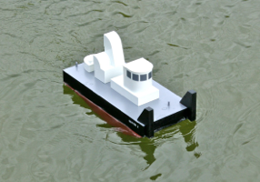
A recent popular project originating from the USA is the Springer Tug. This is a little pusher tug built to a standard design, and designed for the hurly burly of playing football on the water.
While the design of the hull is based on a set of standards for the length, width, profile and rudder area, the superstructure can be constructed to suit the builder’s own preferences.
There is a list of internet sites providing resources for Springer Tug builders, at the end of the Feature.
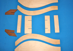
The basic parts are simple, and the hull is cut from 6mm ply.
The shape of the hull side was drawn on a large sheet of paper, then transferred to a sheet of ply using transfer paper (like the old carbon paper we used to use in typewriters). It could just as easily have been drawn directly onto the ply.
Hull sides were cut out using a fretsaw, then sanded while clamped together, to get the curves just right.
The shapes of the internal formers were worked out from the plans and checked against the actual parts.
Although the shape of the hull sides is fixed, there is freedom to add internal bulkheads (or not), to suit your own taste.
To help with skinning the hull bottom, there are two internal formers running fore and aft, made from 3mm ply. This simply prevents the thin ply bottom from buckling inwards as it is curved to fit the hull. Formers were joined using half-lap joints.
The little triangular pieces are for the motor mount and the servo platform. Cut outs are to allow removal of the batteries once the deck is on.
A piece of dowel was drilled axially, to support the shortened rudder tube, and braced against the stern and adjacent former.
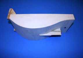
The two big bumpers at the front are made of solid wood, then skinned, later, in thin ply.
The hull of this model was skinned in two sections, because of the width of the sheets available, and it was an easier way of coping with the return bend. You can see the join in the picture above, just under the prop tube. Hull skins are glued with Araldite, and pinned with small brass veneer pins.
The skeg is solid and flat, and will have a brass strake added later.
The peculiar shape of the hull mimics real life. Yes; there are full-sized tugs with hulls of this shape.
The former at the front is glued and screwed to the back of the bumpers.
The bottom of the former is chamfered to match the hull, and it is easier to mark off for the chamfer before skinning the hull bottom, by cutting the former to width and holding it in place.
Leave it a little tall, at that stage, and mark the actual height, then trim it later (but before glueing it in position).
The apertures are theoretically to allow drainage, but since they don’t reach the hull bottom, they won’t work unless there is a lot of water (in which case, the boat will have sunk...). They also serve to lighten the construction, which was already tending to be heavy looking.
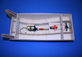
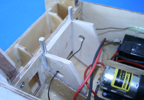
The motor has to be a 540 size, according to the design specification. This one is mounted on a 2.3:1 Olympus reduction drive, from Redbank Models.
Huco coupling; 4mm x 5 inch long shaft and a Raboesch brass 35/3 left handed prop.
Shaft and prop are from SHG Model Supplies.
The servo is a Hitec HS 311 and the rod end couplings are ball ended aircraft couplings, to allow for horizontal misalignment (not that they are, of course; just that they might be), and any misalignment WILL strain the servo.
Using two rods allows the servo to pull as well as push the rudder, and eliminates any tendency for the rods to buckle.
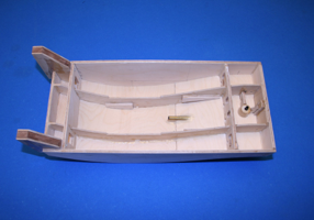
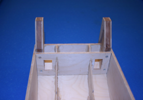
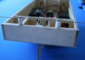
Front and rear posts are glued into the inner corners at the longitudinal formers. They are trapped there by extra sheets of 6mm ply which effectively form bracing boxes in the outer compartments. This helps spread any load from the posts when pulling another boat.
The posts have flats filed along their sides, to help prevent rotation, once the glue is introduced.
To set the height of the posts, two Delrin or Acetal plastic tubes were made as a jig. Araldite will not stick to Delrin or Acetal.
The post holes were aligned using the rod shown in the picture.
The front posts, and their reinforcing plates, come close to the motor mount. The breadth of the plates is to support the deck, but the motor mount needs to be able to move backwards, if you have to remove the motor, because of the coupling.
Cut slots in the plates, near the bottom, or instal the plates short of the bottom, to allow the motor plate to slide backwards to disengage the coupling.
Later, I put slit tubing down the rear edges of the reinforcing plates, to prevent the battery cables from rubbing.
Use heavy duty silicone covered cables, and 6mm or 1/4 inch push on connectors as used in cars. You will need some twin (or piggy back) versions of these connectors.
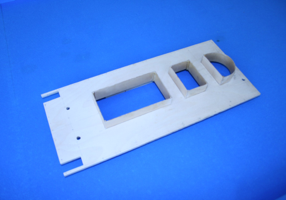
The deck is of 6mm ply, and it was secured with Araldite and brass veneer pins (in pre-drilled holes).
Hatches were cut over the motor, servo/receiver/speed controller, and rudder arm positions, to allow accessibility.
Tall 25mm coaming was glued around the inside of each hatch. These Springers can get mighty wet, and this one often runs with the front of the deck completely under water, so effective coaming is essential.
Tall coaming allows box-shaped hatches with superstructure to slide on and off easily but securely.
Take care when marking out the positions of the holes for the posts. Or use filler, afterwards.
Transfers were applied (Letraset) and oversprayed with 3 coats of gloss varnish, using the airbrush.
Finally, the whole hull was sprayed with a coat of matt varnish.
The initial coats of gloss varnish, lightly de-nibbed between coats, provide a smooth surface for the transfers, and the following coats of gloss help seal the transfer against the water.
The final coat of matt just tones everything down, and blends everything in.
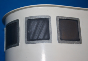
The windows are not glazed, but are simply surrounds, glued directly to the cabin.
Windows were painted using gunmetal paint, and polished using a cotton bud, to give stripes which look like reflections from glass, looking into a dark interior (well I think so anyway). This saved a lot of time.
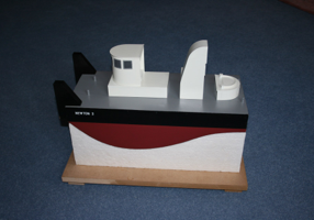
There is little detail on the superstructure at this point. It was more important to get the boat ready for the water, to build a little more enthusiasm. The detail is a joy; but getting too involved with detail too early might delay the meeting between boat and water.
The overall effect, at this stage, is of a simple, blocky boat, and that is probably appropriate.
There are lots of detailed bits lying on the bench, to be painted and added later, which may bring the basic boat to life.
Because of the problems caused by the epoxy coatings on the hull, this was not quite as quick a build as it might have been, but then when was a project like this ever really accomplished swiftly?
As a stand-off model, it is fine, for now.
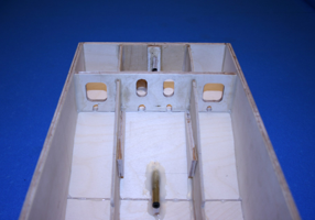
The rear bulkhead has two large lightening holes. It also has two large slots for the rudder control rods to pass through.
The little holes at the bottom are drainage holes, just in case the water gets into the rear compartment.
On this model, they were an afterthought, and were cut with some trepidation after the hull had been glued together. In this thickness of ply, this close to a thin bottom skin, this is an operation not for the faint-hearted. It is easy to cut them before glueing. Should have put more thought into it...
Araldite around the prop tube was thickened with micro balloons; light and fluffy, but very effective. Use real Araldite.
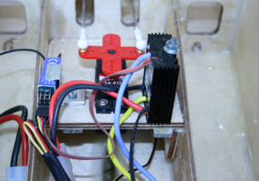
The servo arm carries the ball end posts upright, with the ball ends on top, making for easy disassembly.
The rudder post was left as long as possible, to give as much support to the rudder tube as possible. The tube has been shortened, and needs support against flexing.
The rudder arm comes close to the underside of the deck, so the posts and ball ends are mounted underneath. The ball ends are quite secure, so this works just fine.
These ball ends are a superb way to cope with any small differences in height or alignment which can cause normal ends to bind of jack themselves off, as the rudder turns.
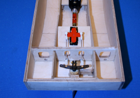
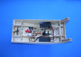
Two 6 volt 4Ah sealed gel batteries were installed in the outer compartments. They are wired in parallel, to give 6volts at 8Ah; enough for hours on the water.
If you are adding formers, you do need to consider the size and shape of the batteries before you fix the formers in place.
The electronic speed controller is mounted vertically, under a hatch position, on the servo platform.
The receiver is also mounted on the servo platform, using a small home-made clip to allow easy removal.
The aerial passes around the hull, through some holes in the formers. Drill them before installing the formers.
The speed controller stands vertically, for two reasons:
firstly, there wasn’t much space. Nearly all of the little platform is accessible under a hatch, and the nut on the rod securing the controller is easily accessible in this position.
Secondly, vertical fins may radiate heat upwards a little better.
The controller is likely to get hot, and the hatch has two functioning mesh grilles to allow ventilation to stop the controller frying.
As a bonus, the programming button on the controller is near the top, so it is more easily accessible.
There is an aluminium plate under the platform, and the threaded rod screws into a tapped hole.
The hull was coated inside with epoxy (West System) before the deck was glued on. The underside of the deck was also coated beforehand.
Once assembled, the outside of the hull was painted with epoxy. Nightmare. Absolute nightmare. Loads of rubbing down. 3 coats of epoxy.
Painting was begun with Halfords primer filler, then grey primer to kill the strong yellow of the primer filler.
The bottom and sides were then sprayed with enamel paint: red Norfolk anti-fouling (White Ensign Models) and matt black (Revell no. 9).
The deck was left resplendent in its grey cellulose primer.
Then 3 coats of gloss varnish, well thinned.
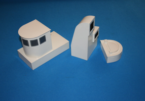
Superstructure design was based around simple boxy shapes.
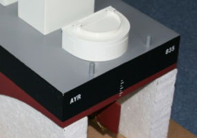
The strange funnels carry functioning metal mesh in 1/35 scale, from Accurate Armour, and help provide ventilation for the inside of the hull.
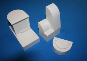
The shape of the cabin is reflected in the rounded shape of the rear platform (which is for the tow hook), and the curve of the funnel/ventilation stack was similarly inspired.
There are some small reinforcing strips under the flat platform on which the cabin sits, but they were probably unnecessary.
Curved plastic sections are best supported with appropriate formers on the inside of the curve, otherwise, the sheet can flex inwards as it bends to form the curve.
The cabin has a floor and a curved inner piece at the top (both slightly smaller overall than the roof of the cabin) and the cladding sheet wraps around those formers.
The sheet was softened in hot water and pre-bent by wrapping around a big tube, before finally fixing around the formers.
The funnel/ventilation stacks have ribs running across from one side to the other, to support the bent outer sheet.
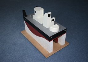
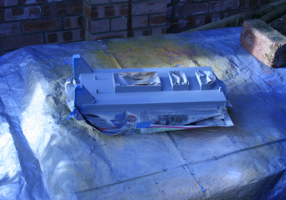
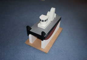
The stand is a simple thing, with tall foam sides, and MDF base, and little feet to allow fingers under the ends when lifting the whole lot at the pondside.
The foam was from a sheet of thick insulation foam, and building it this way meant it was easy to mark out the shape just by laying the boat on its side, on the foam sheet.
The foam was cut with a powered fretsaw running at a medium speed with a coarse pitch blade.
It’s not supposed to be an exhibition piece, but it is functional and it won’t matter if it gets bashed in use. Something smarter is required for display on the sideboard.
The front bumpers really need some serious padding, perhaps using rolled up pipe insulation or strips of foam, and the boat needs a rubbing strip all around the hull.
Tyres might be a good idea, and we need horizontal bars through the capstans.
This version of the Springer has no gunwales, which turned out to be interesting because the hull has a tendency to submarine at top speed. On the other hand, the water runs straight off again.
Every one is different, and that’s part of the fun.
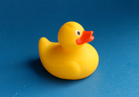
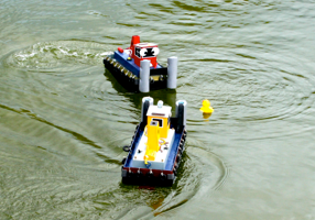
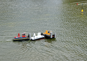
The main idea is to play football, or, in our case, duck sweep, in which a hi-viz duck is captured between the Springer’s front bumpers and guided towards a dock.
The more Springers attempting the same task at the same time, the more fun/argument/bumping/hooligans involved.
Some may say this is not scale model boating, and certainly not the kind of sailing undertaken by gentlemen, and, to be honest, they’d be right.
Does that mean they are content to be on the duck’s side (run those last two words together...)?
Resources
Plans: http://nwrcsm.freeyellow.com/springer.PDF
Examples: www.rcgroups.com/forums/showthread.php?t=522762
Props and shafts and batteries and 540 motor: www.shgmodels.com
HUCO coupling, servo, rudder, ply, speed controller, receiver, crystal and bits & bobs: www.paisleymodelcentre.co.uk
Olympus 2.3:1 speed reducing drive unit; fan cooling unit for 540 motor: http://quantrum.co.uk/redbankmodels/